Description
I submitted the V2 PCB (ESP32DIV2-Gerber.zip) to a PCB manufacturer for prototyping, and their DFM team flagged an issue: the 4 circular features at the board corners appear to be intended as mounting holes, but they only have solder mask openings (copper pads) with no corresponding drill holes.
What I found in the Gerber data
| Layer / File |
What's there |
What's missing |
| GTS (Top Solder Mask) |
Circular solder mask openings at all 4 corners (copper exposed) |
— |
| RoundHoles.TXT |
Various PTH/NPTH holes |
No drill defined at the 4 corner positions |
| SlotHoles.TXT |
8 plated slots (for shield connector) |
— |
| DRR (Drill Report) |
T7: 4× NPTH 24mil, T8: 2× NPTH 35mil |
No NPTH at the 4 corners |
Visual comparison
3D render from design: The 4 corner pads appear as circular copper areas with no through-hole visible.
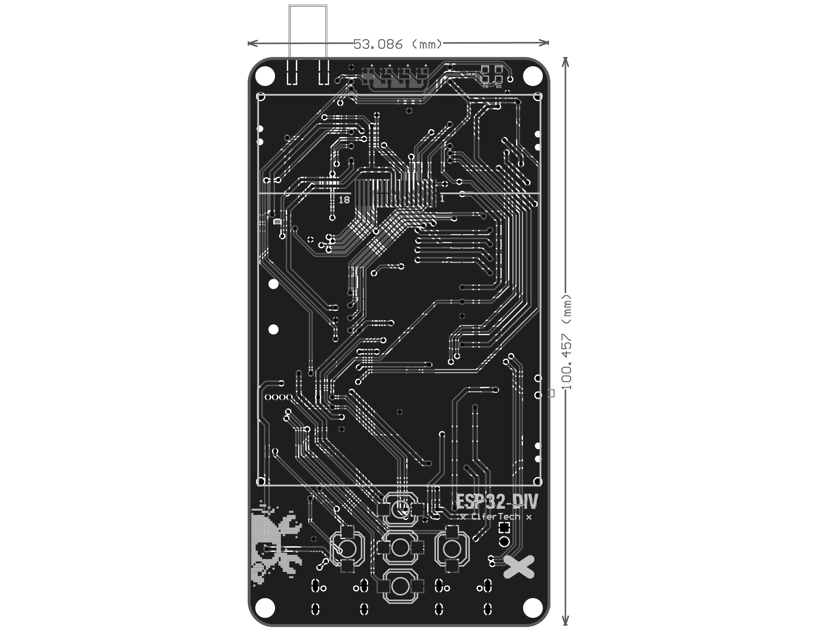
Manufacturer feedback: The 4 corners look like they should be mounting holes but aren't drilled through.
Suggested fix
In Altium Designer, add NPTH (Non-Plated Through Holes) at the 4 corners:
| Parameter |
Suggested value |
| Hole type |
NPTH (non-plated, mechanical only) |
| Diameter |
3.0mm (M3 screw) or 2.5mm (M2.5) |
| Position |
Centered on the existing solder mask openings at the 4 corners |
| Copper pad / solder mask |
Keep existing — they're already correct |
If 3.0mm is too close to the board edge, I'd recommend 2.5mm NPTH (M2.5 screw), which is the most common size for handheld device enclosures of this scale.
Additional context
The slot holes (T2, 8 plated 24mil slots) in the Gerber are for the shield board connector — these are unrelated to the mounting hole issue.
The board dimensions are approximately 52.5mm × 100mm (2.07" × 3.94"), consistent with a handheld device that uses a 3D-printed enclosure requiring screw mounting posts.
Description
I submitted the V2 PCB (ESP32DIV2-Gerber.zip) to a PCB manufacturer for prototyping, and their DFM team flagged an issue: the 4 circular features at the board corners appear to be intended as mounting holes, but they only have solder mask openings (copper pads) with no corresponding drill holes.
What I found in the Gerber data
Visual comparison
3D render from design: The 4 corner pads appear as circular copper areas with no through-hole visible.
Manufacturer feedback: The 4 corners look like they should be mounting holes but aren't drilled through.
Suggested fix
In Altium Designer, add NPTH (Non-Plated Through Holes) at the 4 corners:
If 3.0mm is too close to the board edge, I'd recommend 2.5mm NPTH (M2.5 screw), which is the most common size for handheld device enclosures of this scale.
Additional context
The slot holes (
T2, 8 plated 24mil slots) in the Gerber are for the shield board connector — these are unrelated to the mounting hole issue.The board dimensions are approximately 52.5mm × 100mm (2.07" × 3.94"), consistent with a handheld device that uses a 3D-printed enclosure requiring screw mounting posts.